A Seven-Segment Display in MARS
This is an actual device that we can control with a MARS program.
- Run MARS and pick "Digital Lab Sim" on the Tools menu.
- This will give you a small window that floats in front of the normal MARS window.
- On the left side are two seven-segment displays; on the right side is a keypad.
- We're not interested in the keypad, but the seven-segment displays are the ultimate simple I/O device.
- There are actually eight segments counting the dot.
- The byte at address 0xFFFF0010 controls the right display,
and the byte at 0xFFFF0011 controls the left one.
- Notice that these addresses are above the top of memory (which is at 0x7FFFFFFF).
- The CPU can do loads and stores to these addresses as if they were memory, but the result is that things
happen in the seven-segment displays instead of the results
that we expect from loads and stores to memory
- This is called Memory-Mapped Input/Output, which we can write MMIO for short.
- This line of code: .eqv RIGHT_SEGS 0xFFFF0010 means that, when we write RIGHT_SEGS,
the assembler will use the value 0xFFFF0010. This makes the program more readable.
- Each bit in the byte controls one segment in the display; 1 lights it up, and 0 turns it off.
- Download 7seg0a.asm from OAKS and open it in MARS.
- Assemble it, push the "Connect to MIPS" button in the "Digital Lab Sim" window, and run the program.
- You should see the individual segments in the right display light up one at a time.
- The program is writing bytes into 0xFFFF0010
(the controller for the right display) at one-second intervals.
- Each byte that it writes has one 1 bit and seven 0 bits, and the location of the 1 bit changes each time.
- first the 1 bit is bit 0; then it is bit 1; then it is bit 2
- etc. etc. etc.
- This lets us see where we need a 1 bit to light up any particular segment.
Here is a picture of the word at address 0xFFFF0010 and one of its seven-segment displays
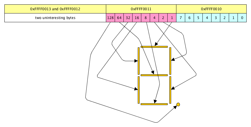
- We are interested in only two of the bytes in this word.
- The addresses of the bytes are in the accompanying yellow boxes.
- The arrows point from the position of a bit to the segment that it controls.
Let's be really careful about how information is displayed in this drawing
- In the byte at 0xFFFF0010 (blue) the numbers in the small boxes are bit numbers: 0 ... 7
- In the byte at 0xFFFF0011 (pink) the individual bits have the same numbers as in the other byte,
but that's not what is displayed here. Instead, what we have are the actual values of a 1 bit
in that position. This value is in fact 2 to the power of the bit position, and
it doubles each time the 1 bit moves left by one place; we've known this for a while.
- That's exactly what 7seg0a is doing: moving the 1 bit left,
one place at a time. It is doing this by copying
successive bytes from the array segments; notice that the values of these
bytes double as you move across the list in the source code for the data segment.
- Now try 7seg0b.asm; it produces the same output but, instead of copying bytes from an array,
it uses a shift instruction to move the single 1 bit left.
We can display characters by lighting up the correct collection of segments at the same time.
- We do this by storing more than one 1 bit into the control byte.
- Storing 2 will light up the upper vertical bar on the right; storing 4 lights up the one below it.
Storing 2 + 4 = 6 lights up both of them, and we display a "1". Storing 63 lights up all
but the center bar, so we get a "0".
- In general, we can decide what value we need by taking the set of segments we want to light up,
following the arrows back to the pink boxes, and adding the values we find there.
- Download 7seg1a.asm from OAKS, open it in MARS, assemble it, choose "Digital Lab Sim" on the Tools
menu, click "Connect to MIPS", and run the program.
- The left seven-segment display will show, in order,
"0", "1", "2", "3", "4", "5", "6", "7", "8", "9", "A", "b", "C", "d", "E", and "F".
- Check the values in the array at digitos. You should be able to verify that the numbers
in this array are the correct combinations to display the digits that you see when the program runs.
- What value would we store in order to display the letter "H"?
- Download 7seg1b.asm from OAKS and run it (using all the steps listed above for 7seg1a).
It will let you type in any byte value (0 .. 255) and show you which segments that value will light up.
Try some powers of 2 and notice that you always get a single segment lit that way.
Try some other numbers and check to be sure that you get what you expected.
Try your answer to the H question.